Roll-up a door please!
(with a State Machine in code, part 1)
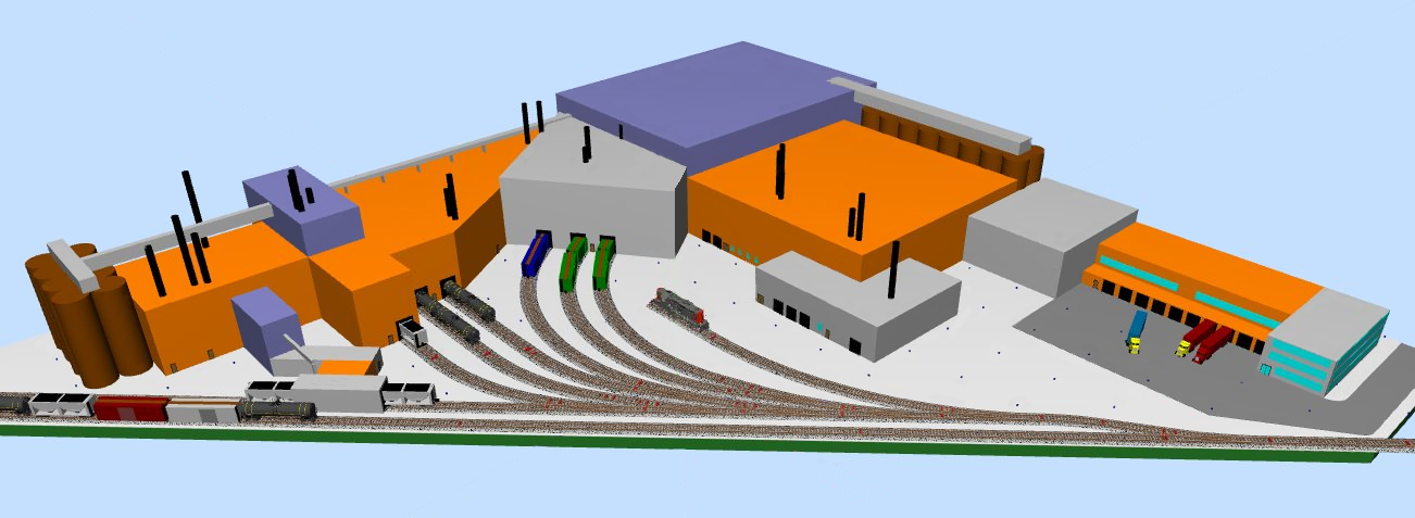
MHO Junction’s Molson Brewery in a 3D Layout View (all photos and drawings by Lloyd Henchey, Ontario, Canada)
We all know we can open and close close something with an Arduino and a Servo, but what if we want to a little bit more operating fun with some lights and sounds, all after a manager gives approval to open or close the door to the beer brewery before your engine is allowed to pick up or deliver a car?
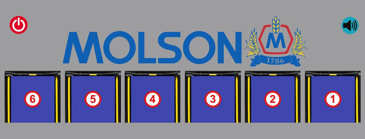
Control Panel at the brewery
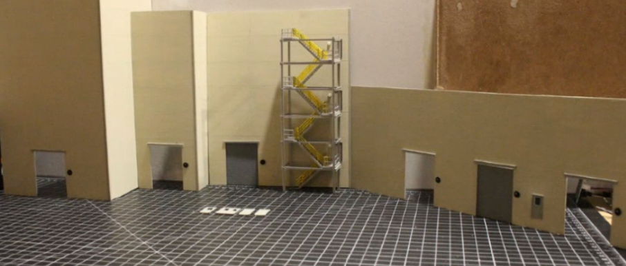
Six doors under construction at the Molson brewery on the MHO Junction
Engine pulls up to the red light, shift manager (operator) grants permission, door raises up with alarms and a flashing red light, door goes all the way up, light turns green, engine or car can proceed! Same flashing red light going down and maybe different door squeaking noises.
All good articles start with a YouTube video: youtube.com/watch?v=-8EnpUgTqR4 !

This article will introduce you to a “Finite State Machine” or FSM, where you describe or plan everything that needs to happen with circles for states where things are in and with lines and arrows for when things happen.
What you need (all the links embedded here, but also typed out at the end of this document, in case you printed the article and can’t click on it here):
An Arduino Nano with a USB mini-B cable (or Uno will do, but the Nano is less expensive)
Something to power it with, since you can’t leave that borrowed PC in the train room.
To avoid soldering and splicing wires:
Nano I/O Expansion Sensor Shield Module has more than enough ground pins, one with each I/O pin.
And:
A small servo for every door you need to open, we can do 3 if your power supply has enough “oomf”.
A button, key, light sensor or infrared sensor used for input for every door you need to allow access or interrupt light to open the door.
A common cathode bi-color 3mm LED and 2 resistors, 1 kOhm each (at first), one set for each door.
Optional sound system from last article with an MP3 uSD card and 3 sound files!
And as before,
The Arduino IDE, free download Version 1.8.13 is the latest at the time of writing.
Maybe the CH340 Device Driver: plug the Nano in with the USB cable and see if Device Manager gives you a Serial COM port (/dev/ttyACMx or /dev/ttyUSBx on a Mac or Linux). If Windows shows you a yellow icon, find the driver with Google, download and install the driver and then reboot the computer.
And last, but not least, the code to install for this project.
With all the bells and whistles, we need 5 pins per door (and two more to turn sounds on and off):
Input: access granted, a simple, normally open push button for the manager.
Output: the red signal, like a 3 mm or smaller red LED in a black disk.
Output: the green permission granted LED, which, combined with the red one, could be a bi-color LED as used in a search light.
PWM Output: the door’s motion is controlled with a servo, needing a PWM capable pin to control this.
Output: an optional output pin to turn some sounds on, using the uSD card mp3 player from the last article (a serial interface might work better, so either a software UART or a clock and data pin, we’ll do this instead). So two pins (RX and TX) for the whole system.
In order to start planning the code, we draw up a finite state machine. A state machine represents all the states your door and lights can be in and it shows how it transitions from one state to another based on what input has changed. Of course there are 3 sets of these, one for each door, sensor and signal...but since they do not have anything to do with each other, we only need to draw one of the sets. Oops, feature creep, we only want a door to open if the other doors are all closed. So we will not leave that state unless all doors are closed.

FSM (Finite State Machine)
In our setup the door only opens on startup or with manager approval. All good state diagrams start with a darker circle to show where it all begins, Power On in our case. The dotted lines indicate actions that happen without human intervention, from Power On, it goes to the next state, POST, by itself, and so forth.
Again, from Power On, we move immediately to the POST (Power On Self Test) where we check if the sound module is happy, uSD card inserted and we play the first sound file as a part of the test. From here the state diagram transitions to the “Door Opening, Light Flashing Red” state, simply to avoid an accident when the power went out at the wrong time. We flash the red light and play the second sound file.
When a door is completely opened, the flashing red light will turn green, now in the “Door Open, Light Green” state. And this will happen to all the doors, but is not shown. Just know that not all doors have to be in the same state at the same time. It is only on power up that we send them through the same states.
Here the Arduino waits for the Manager to press and release one or more of the Approval Buttons for each door. Upon press and release, the specific door will start closing, with the red light flashing and the “closing” sound playing, shown in the “Closing Door, Light Flashing Red” state.
Once closed, we enter the “Door Closed, Light Red” state, with the light now solid red (you could also change the requirements and have the light turned to off). Also note that not all our doors have to close at the same rate, or from the same height, so some might be closed before others.
From here, only one door can be opened at one time due to safety regulations at the plant. Silly rule, but the union is in charge, sorry. When the button is pressed for any door, it will only move to the “Door Opening, Light Flashing Red” state if all were closed. If the button is pressed and there is already an open door, we stay in the same state. But, if all closed, the door starts opening, flashing the light red, and we are back where we started when the power turned on, except only one door can be here now.
The state machine keeps the current state each door is in, and only moves to another state when the input with the line and arrow leaving the circle gets activated. There is no “Door Closed” or “Door Opened” sensor, but the software inside knows the position of the door, since it is setting the servo position, and compares it to the commanded position. When a door reaches the open or close commanded position, the state machine follows the dotted line automatically to the next state.
For part 1 of this article, we only show the wiring and code needed for 1 door to keep it a little shorter. You wire up the servo, the push button (approval) and the bi-color LED. We want to use a PWM pin for the servo, since we don’t want the extra code needed for a software servo (just know that you could control a servo from any pin). PWM pins, those labeled with the ‘~’ (tilde) symbol (D3, D5, D6, D9, D10 and D11) make life a bit easier.
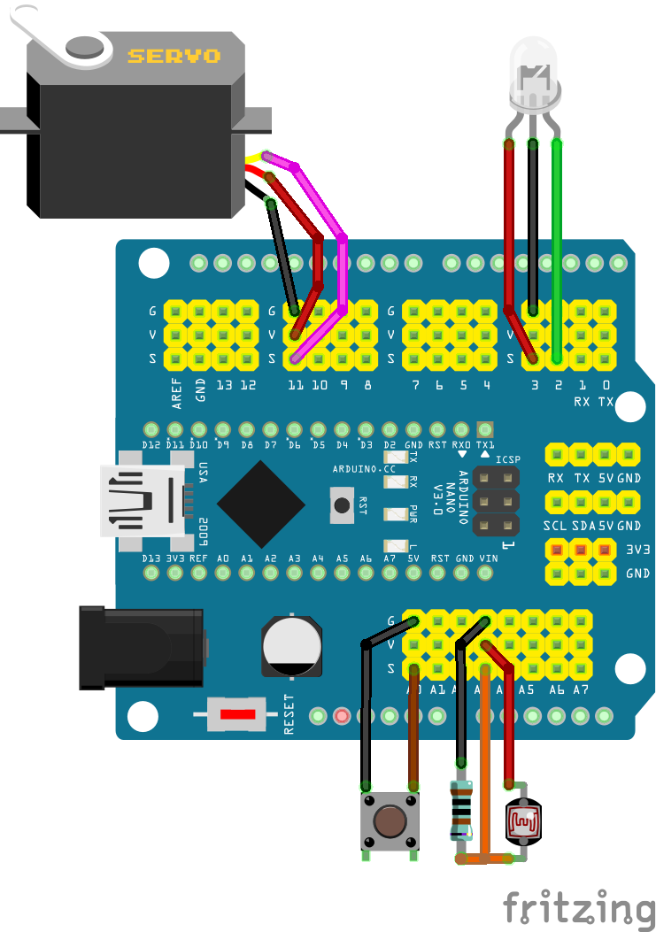
Servo, bi-color LED and button connections to a Nano on the Expansion Board (thank you fritzing)
(The light sensor shown is another feature creep for a future article to dim the lights a bit at night time)
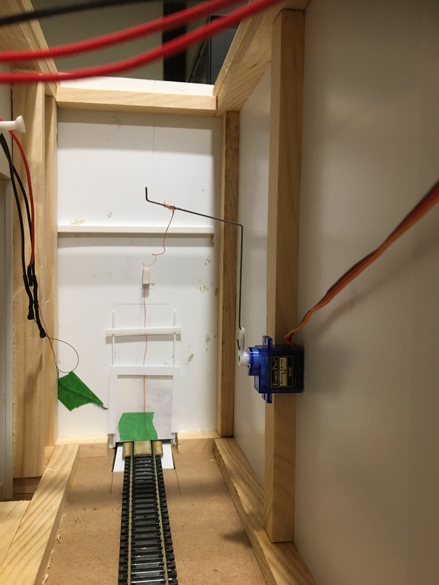
Servo installed behind the brewery door
Back to the State Machine, how do we create and use it?
First, you create an enumeration or enum for short to indicate which state you are in. This is literally just assigning a number to a word for each state (DoorOpening) that is a lot easier to read in the code, than remembering it with a number, like 4 for “Door Opening, Flashing Red Light”. So enum defines a new type in C or C++, so just like you have int, bool and Serial or Servo, after the next few lines of code, you will also have DoorState as a type.
enum DoorState {
POST = 0,
DoorOpening,
DoorOpen,
DoorClosing,
DoorClosed
};
And then we use this to create an array of DoorState types, to keep track of the state for each door.
#define NUM_DOORS 3
DoorState breweryDoorStates[ NUM_DOORS ];
Technically, we won’t use the POST state much, since we think of it as the code that runs in the setup( ) routine, which only happens after Power On, or if someone pressed the Reset button. Just note that the code won’t set it back to POST ever again. Setting and checking the states, here we go:
#include "SlowDoors.h"
#include "BreweryLites.h"
#define NUM_DOORS 3
enum DoorState {
POST,
DoorOpening,
DoorOpen,
DoorClosing,
DoorClosed
}; // all these need to be unique words and not strings used in the C/C++ language or your code.
// Example: setup is not allowed -> error: 'setup' redeclared as different kind of symbol
DoorState breweryDoorStates[ NUM_DOORS ]; // State Machine for each door
// SlowDoor( uint8_t servoPin, unint8_t buttonPin, uint16_t start, uint16_t stop, uint16_t updateRate )
SlowDoor *breweryDoors[ NUM_DOORS ] = {
new SlowDoor( 3, A0, 70, 120, 50 ),
new SlowDoor( 5, A1, 75, 125, 50 ),
new SlowDoor( 6, A2, 60, 180, 30 ) // servo moves a little faster, since further travel
};
//BreweryLite( uint8_t redPin, uint8_t greenPin, uint16_t flashRate )
BreweryLite *doorLites[ NUM_DOORS ] = {
new BreweryLite( 7, 8, 500 ),
new BreweryLite( 9, 10, 400 ), // flash a little faster
new BreweryLite( 11, 12, 500 )
};
void setup( ) {
Serial.begin( 115200 );
Serial.println( F("\nRoll-up Doors version 1.0, 2020.11.01") );
for( uint8_t i; i=0; i<NUM_DOORS ) {
breweryDoorStates[i] = POST;
breweryDoors[i]->Setup( ); // attach servo pin and INPUT_PULLUP button pin
doorLites[i]->Setup( ); // pinMode both LED pins as OUTPUTs
} // for
// setup DFPlayer (not shown, see prior article)
// play 001.mp3
} // setup( )
void loop() {
// For each door, use switch to manage the state machine
for( uint8_t i; i=0; i<NUM_DOORS ) {
switch( breweryDoorStates[ i ] ) {
case( POST ):
// if playing, stop and play 002.mp3
breweryDoors[i]->Open( ); // command the door to ...
doorLites[i]->FlashingRed( ); // command the light to ...
breweryDoorStates[i] = DoorOpening; // new state is ...
break;
case( DoorOpening ):
if( breweryDoors[i]->isOpen( ) ) { // check if the door is ...
doorLites[i]->Green( ); // set the light to ...
breweryDoorStates[i] = DoorOpen; // new state is ...
} // if
break;
case( DoorOpen ):
if( breweryDoors[i]->wasButtonPushed( ) ) {
breweryDoors[i]->Close( );
doorLites[i]->FlashingRed( );
breweryDoorStates[i] = DoorClosing; // new state is …
// if playing, stop and play 003.mp3
} // if
break;
case( DoorClosing ):
if( breweryDoors[i]->isClose( ) ) {
doorLites[i]->Red( );
breweryDoorStates[i] = DoorClosed; // new state is ...
} // if
break;
case( DoorClosed ):
if( breweryDoors[i]->wasButtonPushed( ) ) {
// count number of closed doors
uint8_t closedCount = 0;
for( uint8_t k; k=0; k<NUM_DOORS ) {
if( breweryDoors[k]->isClose( ) ) closedCount++;
} // for
// and only open if all are closed
if( closedCount == NUM_DOORS ) {
breweryDoors[i]->Open( );
doorLites[i]->FlashingRed( );
breweryDoorStates[i] = DoorOpening; // new state is ...
// if playing, stop and play 002.mp3
} // if all closed
} // if
break;
default: // should never get here
Serial.println( F("oops...") );
break;
} // switch
doorLites[i]->Update( ); // update the lights, green, red or flashing
breweryDoors[ i ]->Update( ); // update the servo to move a step closer
// or stay at its commanded position
} // for
} // loop( )
Note that we only have one sound player, and whichever action happens last, will stop the previous sound and start the sound just requested. Not perfect, but better than nothing, I guess!
Once you have all this working, you can add a few more things like checking if the track under the door is clear before closing it. You could mix some sound files on your computer and play the sounds for opening and closing a door at the same time. You can disable the sounds after 3 or 4 times for those of us who are not fond of screaming alarms, or have an enable/disable input to turn it on and off. Or you could install and enable that light sensor to change the brightness of the red and green light? The height of the door is the limit!
Speed
LINKS:
An Arduino Nano:
https://smile.amazon.com/REXQualis-Board-ATmega328P-Compatible-Arduino/dp/B07WK4VG58/ref=sr_1_1_sspa
Power it:
Nano I/O Expansion Sensor Shield Module:
https://smile.amazon.com/WYPH-Expansion-Arduino-Compatible-Duemilanove/dp/B07KCVJ6RR/ref=sr_1_3
Small servo:
https://hobbyking.com/en_us/hobbykingtm-hk15178-analog-servo-1-4kg-0-09sec-10g.html
Light sensor:
Infrared sensor:
https://www.amazon.com/Willwin-Infrared-Obstacle-Avoidance-Intelligent/dp/B0776RCLH6/ref=sr_1_8
3mm bi-color LED:
1 kOhm resistor:
https://smile.amazon.com/Noblik-0-25W-Carbon-Resistor-Postage/dp/B085PVRV7V/ref=sr_1_2
Arduino IDE:
https://www.arduino.cc/en/Main/Software
Sound system in prior Marker Lamp:
https://archive.org/details/marker_lamp_winter_20/page/n12/mode/1up
Finite State Machines: https://brilliant.org/wiki/finite-state-machines/