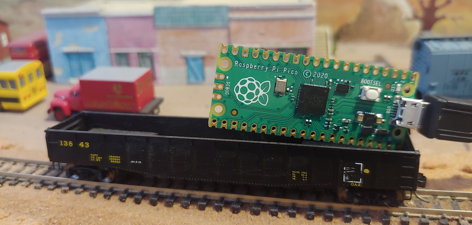
Pi Pico on an N-scale gondola
Pi Pico, we smell competition in the land of the ‘duino!
Our very favorite low cost microcontroller system is seeing some fresh competition. Everyone by now has heard about the Raspberry Pi, some fruity company in the United Kingdom, making single board computers! They run Raspbian (or other flavors of Linux and are capable of some Windows versions) for as little money as $10 for the Pi Zero W. The more popular Model 4, with 2 GB of RAM, retails for about $29. Add a $5 micro SD card and you have a real computer with which you can surf the internet, write code and even program Arduinos. It also runs our other favorite, JMRI. Of course, plug it into a small or big screen television with an HDMI cable and you can even stream Netflix. If you want a really cool computer built into a keyboard, also check out the brand new, Raspberry Pi 400, you might just think you own a ZX Spectrum again.
These are all “computers” with processors and now the Raspberry Pi Foundation has ventured into the microcontroller (MCU) market with their first chip, the RP2040. They also put it on a board (2” x 0.82” x 0.15”) about the size of an Arduino Nano, and called it the Raspberry Pi Pico. Micro Center had it stock right after the announcement and is selling it for $3.99, but to lure you into the store, you can get the first one for a mere $1.99!
So, before putting you to sleep, what makes this new Pico board better or worse than the Arduino Nano?
First, you get 2 cores, or “brains” in the same silicon part, only 1 exists in the Nano
32-bit ARM Cortex-M0+ parts compared to the Uno or Nano’s 8-bit RISC architecture in the Atmega328P
runs quite a bit faster, 48 MHz (and can go up to 133 MHz) compared to 16 MHz in the Nano
264 kBytes of RAM, versus the Nano’s 2 kBytes
2 MBytes (up to 16 MBytes) in a separate chip, while the Nano only has 32 kBytes to store your code
No EEPROM present as realized with 1 kByte on the Nano
The Pico can be programmed very easily with MicroPython, and both can also be programmed using C or C++
The Pico MCU runs on 3.3 Vdc where the Atmega328P is 5 Vdc capable. I only call it a slight negative, since you might have to change some of your external circuits to work with the 3.3 V
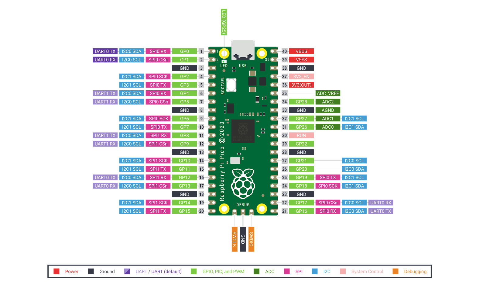
It has 26 I/O pins against the 20 I/Os on the Nano, six more is always welcome
It only has 3 analog input pins, but at 12 bits, against the 6 analog pins sampled with 10 bits
Another eyebrow raiser is the 16 PWM pins compared to the 6 PWM pins, marked with the ~ on the Nano boards, yes sixteen hardware controlled servos!
2 UARTs (serial ports) versus the 1 UART that is connected to the USB converter chip, thus shared, on the Nano
And the technical connections like USB 1.1 supports Device and Host, it has 2 SPI ports, 2 I2C ports where the Nano only has 1 SPI and 1 I2C port
Also a built in temperature sensor on the chip, but easier to use. (The Nano has one too, did you know?)
The onboard LED is on GP25, with no pin on the board to it, and the Nano has it on D13 with a pin for it too
The Pico board does NOT have a power LED on board, and the Nano, Uno and several others do. This is quite unsettling if you like to know your board is powered before and after you program it!
The Pico also has 8 state machines in something called Programmable I/O, so you could imagine seeing DCC decoders being decoded by hardware in the chip self. This might avoid the normal software routines written in ASM code, so you might be able to use DCC just as easily as you would use I2C or a UART
But the Pico board has the silkscreen labels on the BOTTOM and almost ALL Arduino boards have them on TOP
9 ground pins spaced at the 3rd pin from each corner and 4 other pins in between down the long sides and the middle pin on the short side, versus a desperate search for more than the 3 ground pins on the Nano! (Yes, the Nano’s 6 pin header on the short side also has a GND pin)
1 BOOTSEL button (This enable flash drive mode when pressed at powerup and does not reset your Pico when your code is running, with care, you can use this button as an input), versus 1 RESET button on the Nano
Micro-B USB connector versus Mini-B USB on the NANO, which one is better? Depends on your current or last phone charger, right?
The PICO board comes with “castellated” pins, and no parts underneath the board, so you could solder the Pico down to another board as if it was another part.
So, how do we use this? The easiest first test is to install MicroPython on the Pico and then write some Python code to make the LED blink. When you push the button on the board when you plug it into the USB port, you will put the Pico in a mode where you will get a “Thumb drive” on your computer. D: or E: it might be. On the drive is an html document that, when opening it in your browser, will take you straight to the Pico Getting Started Guide on the Raspberry Pi Foundation’s website. So you don’t need to find the web page first, you need to plug the Pico in first!
Onto this very same drive you would drag and drop the MicroPython.UF2 file and next time you power the Pico up (without pressing the button) it will show up as a Serial Port in your computer and the Pico will be running MircoPython. So opening the Serial Port up in something like Thonny, TeraTerm, putty, rshell (if you like the command line) or even the Arduino IDE’s Serial Monitor, you will see the REPL interface just like you would if you have Python installed on your computer and type “python” in on the command prompt.
A command like print( “hello world” ) would show hello world in REPL, but you could call that a bluff and blame TeraTerm for doing that. So better would be to turn the LED one, right?
So the command prompt in REPL is the >>> so don’t type that in:
>>> from machine import Pin
>>> led = Pin( 25, Pin.OUT )
>>> led.value( 1 )
While you compare this to:
void setup( ) {
pinMode( 13, OUTPUT );
digitalWRITE( 13, HIGH );
} // setup( )
keep in the back of your head that setup( ) still needs to be compiled and uploaded where REPL is actually uploaded to the Pico and executing your code as you type it in. That allows you to fairly quickly try things out and test them, before settling on the final version of the code. But, right now, when you remove the power from the Pico and turn it back on, you are left with only REPL running, and no LED turned on.
To the rescue is the Thonny tool (or the Pico-Go extension if you prefer VS Code) with which you can access REPL as well as having access to the file system on the Pico where you can save your Python (.py) programs or scripts if you want to call them that. To the chase, in order to have your code run on power up, you need to save it as main.py. When you enter code in the Thonny editor, you will have a choice to run it locally on the computer or on the Pico, so make sure it is saved to the Pico as main.py, and, when you turn the power back on, the LED will light up.
“That is quite exciting” you will say, not! A resistor and a battery can make an LED turn on too! So lets blink the sucker, since that is what you really want right? We will avoid the whole delay( ) dilemma holding the Arduino chip hostage, and introduce the Timer concept while using the led.toggle( ) function.
from machine import Pin, Time
led = Pin( 25, Pin.OUT )
timer = Timer( )
def blink( timer ):
led.toggle( )
timer.init( freq=1, mode=Timer.PERIODIC, callback=blink )
And that is it, either execute that on the Pico with Thonny, or save it as main.py and cycle power.
The def blink( timer ): in Python creates a function in Python, just like void myBlink( Timer timer ) { } would in C, and the indentation (spaces) before led.toggle( ) puts the toggle command in the blink function. As soon as the indentation returns to the left, you are out of the function. So no { or } needed. Just the : and the indentation. You will see the same thing with things like if, for and while
if( a == b ):
for( item in myList ):
c = 0
while( c < d ):
print( item )
c = c + 1
Two cores you say, so can we use delay( ) again now? Well you should not, but let’s check this horrible idea out anyway...I want the one core to blink the LED and the other core to print a message on the REPL display. A better idea would be to solder a LED in, but the curiosity is too high!
import time, _thread, machine
def taskToggleLEDOnSecondCore( count, delay ):
led = machine.Pin( 25, machine.Pin.OUT )
for i in range( count ):
led.toggle( )
time.sleep( delay )
print( 'done #2' )
def printMessagesOnFirstCore( count, delay ):
for i in range( count ):
print( '@ step {}'.format( i+1 ) )
time.sleep( delay )
print( 'done #1' )
_thread.start_new_thread( taskToggleLEDOnSecondCore, ( 20, 1 ) )
time.sleep( 5 )
printMessagesOnFirstCore( 10, 1.5 )
This will toggle the LED 20 times on every second, while waiting 5 seconds to print us the numbers 1 through 10 every 1.5 seconds. Question, who finishes first, or is done #1 or done #2 printed first? So you’ll notice that we are using time.sleep( ), the equivalent of delay( ) in MicroPython, which halts or blocks the core until the time expires, but since we run one task on one the 1st core and the other on the 2nd, we don’t see the one block the other. The range( x ) function, that gives you 0, 1, 2 if x==3 and the “for i in” part that picks 0, then 1 and then 2 as it cycles through the loop. The string object in Python has a format( ) function, where the {} in the string is replaced with the parameters specified. i+1 is thus causing the line to print @ step 1 the first time. You will also note that a print( ) function, by default adds a new line to the end, so you won’t see println( ).
Waau, that is a lot of work, why did you not go the C/C++ route? Well, right now you need to install the whole C/C++ SDK (Software Development Kit), which I guess should not be a task that another YouTube video could not assist me with, BUT, I have heard that the Arduino company is working on a new Arduino board that will have the same RP2040 chip on it. And guess what, when that comes out, we will simply open the Arduino IDE, add the board with the Boards Manager and the whole C/C++ kit will come downloading and configuring itself. Call me lazy, yeah right! At least I have patience!!! Edit: I think it already happened
At this point, while we are working hard on getting mqTrains to the world, I am going to let you ask some questions and wait to see if the model train world requires us to change the quarterly article to RRPiPico ...
Next time I will have the Pi Pico driving a few One Wire Signals from JMRI again, unless you have a bigger need?
Speed
LINKS:
Pi Pico at Raspberry Pi Foundation:
https://www.raspberrypi.org/products/raspberry-pi-pico/
Pico Getting Started Guide:
https://www.raspberrypi.org/documentation/pico/getting-started/
$1.99 and $3.99 Picos at Micro Center:
https://www.microcenter.com/product/632771/raspberry-pi-pico
MicroPython .UF2 file:
https://www.raspberrypi.org/documentation/pico/getting-started/static/5d8e777377e8dbe23cf36360d6efc727/pico_micropython_20210121.uf2 <- this might not be valid for long, but the Getting Started Guide will get you to the latest
10 things to know about the Pi Pico:
https://www.youtube.com/watch?v=NiLvGeO9PaU
Temperature Sensor on ADC 4:
https://youtu.be/PYOaO1yW0rY?t=418
Arduino Internal Temperature Sensor:
https://www.instructables.com/Arduino-Internal-Temperature-Sensor/
BOOTSEL pin as input:
https://github.com/raspberrypi/pico-examples/blob/master/picoboard/button/button.c
Thonny:
Rshell:
https://www.youtube.com/watch?v=IMZUZuytt7o
Arduino IDE getting Pico support:
https://www.seeedstudio.com/blog/2021/01/29/arduino-ide-support-announced-for-the-raspberry-pi-pico/
mqTrains:
Raspberry Pi 400:
https://www.raspberrypi.org/products/raspberry-pi-400-unit/